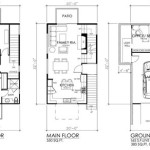
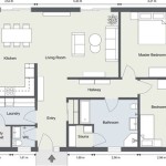
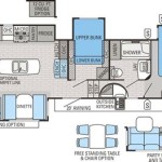
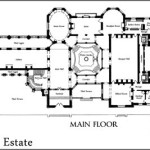
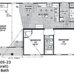
Reading floor plans is an essential skill for anyone involved in construction, architecture, or home design. A floor plan is a scaled drawing that shows the layout of a building from above, indicating the location of walls, doors, windows, and other features. Understanding how to read floor plans is crucial for visualizing a space, planning renovations, or evaluating the functionality of a building.
Floor plans are commonly used in architectural drawings, building permits, and real estate listings. They provide a comprehensive view of a building’s structure and organization, allowing architects, builders, and homeowners to make informed decisions regarding design, construction, and space utilization.
Transition Paragraph:
In this article, we will delve into the intricacies of reading floor plans, exploring the various symbols, conventions, and techniques used to convey essential information about a building’s layout. We will guide you through the process of deciphering these plans, enabling you to interpret them effectively for a wide range of purposes and applications.
To effectively read floor plans, it is essential to grasp the following key points:
- Identify Scale and Dimensions
- Understand Symbols and Notations
- Recognize Wall Types and Openings
- Locate Fixtures and Equipment
- Interpret Room Layouts
- Visualize 3D Space
- Measure Distances and Areas
- Follow Convention
- Consider Context
By understanding these principles, you can develop the skills necessary to accurately interpret floor plans and make informed decisions based on their valuable insights.
Identify Scale and Dimensions
Identifying the scale and dimensions of a floor plan is crucial for understanding the actual size and proportions of the building. The scale indicates the relationship between the size of the drawing and the actual size of the building, allowing you to determine the real-world measurements of walls, rooms, and other features.
- Graphic Scale:
A graphic scale is a graphical representation of the scale, typically shown as a line segment divided into equal parts. Each part represents a specific unit of measurement, such as feet or meters. For example, a scale of 1/4″ = 1′-0″ indicates that one-quarter inch on the drawing represents one foot in real life.
- Numerical Scale:
A numerical scale expresses the scale as a ratio. For instance, a scale of 1:50 means that one unit on the drawing represents 50 units in reality. This type of scale is commonly used in architectural drawings.
- Dimensions:
Dimensions are numerical values that indicate the length, width, or height of walls, rooms, and other elements. They are typically shown as small numbers or labels adjacent to the respective features on the floor plan.
- Measuring Tools:
To accurately measure distances and areas on a floor plan, you can use a scale ruler or a digital measuring tool. Scale rulers are specifically designed for architectural drawings and have the appropriate scale printed on them. Digital measuring tools, such as CAD software or mobile apps, offer precise measurements and the ability to calculate areas and volumes.
By understanding the scale and dimensions of a floor plan, you can visualize the actual size and proportions of the building, ensuring accurate planning and decision-making during construction, renovations, or space planning.
Understand Symbols and Notations
Floor plans utilize a standardized set of symbols and notations to convey information about the building’s layout and components. Understanding these symbols is essential for accurately interpreting floor plans.
Walls and Openings
Walls are typically represented by thick lines, with different line weights indicating the type of wall. For example, a thick, solid line may represent a load-bearing wall, while a thinner line may indicate a non-load-bearing or partition wall. Openings in walls, such as doors and windows, are typically shown as gaps or breaks in the wall lines.
Doors and Windows
Doors are typically indicated by a small rectangle with a line extending from it, representing the swing direction. The type of door, such as a single door, double door, or sliding door, may be specified by the shape and size of the symbol.
Windows are typically shown as rectangles or squares with diagonal lines inside, representing the window panes. The number and arrangement of diagonal lines indicate the number and type of window panes.
Fixtures and Equipment
Fixtures and equipment, such as sinks, toilets, and appliances, are represented by small, stylized symbols. These symbols are typically standardized and may vary slightly depending on the drawing conventions used.
For example, a sink may be represented by a circle with a faucet-like shape inside, while a toilet may be shown as a rectangle with a curved top. Appliances, such as refrigerators and stoves, may be represented by simplified outlines or shapes that suggest their function.
Stairs and Elevators
Stairs are usually depicted as a series of parallel lines, with arrows indicating the direction of travel. Elevators are typically shown as rectangles with a diagonal line inside, representing the elevator shaft.
By understanding the symbols and notations used in floor plans, you can quickly identify and interpret the various components of a building’s layout, enabling you to visualize the space and make informed decisions.
Recognize Wall Types and Openings
Understanding the different types of walls and openings in a floor plan is crucial for comprehending the structure and layout of a building. Walls define the spaces within a building, provide support, and serve various functional purposes.
Load-Bearing Walls
Load-bearing walls are structural walls that support the weight of the building above them, including the roof, floors, and any additional stories. They are typically thicker and more robust than other types of walls and are essential for maintaining the stability and integrity of the building. Load-bearing walls cannot be removed or altered without proper structural support.
Non-Load-Bearing Walls
Non-load-bearing walls, also known as partition walls, do not support any significant weight from above. They are used to divide interior spaces and create rooms, closets, and other compartments. Non-load-bearing walls are typically thinner and less structurally significant than load-bearing walls and can be removed or altered more easily.
Openings in Walls
Openings in walls allow for the movement of people and materials throughout a building. These openings include doors, windows, and archways. Doors are typically represented by a small rectangle with a line extending from it, indicating the swing direction. Windows are shown as rectangles or squares with diagonal lines inside, representing the window panes. Archways are depicted as curved openings in walls.
Understanding the different types of walls and openings in a floor plan is essential for visualizing the structure and layout of a building, evaluating its functionality, and planning any necessary modifications or renovations.
Locate Fixtures and Equipment
Floor plans not only indicate the layout of walls and openings but also show the location of fixtures and equipment within a building. These elements include essential components such as sinks, toilets, appliances, and lighting fixtures. Understanding their placement is crucial for visualizing the functionality and usability of each space.
- Plumbing Fixtures:
Plumbing fixtures, such as sinks, toilets, bathtubs, and showers, are typically represented by small, stylized symbols. These symbols indicate the location and type of fixture, allowing you to assess the availability and accessibility of water supply and drainage in different areas of the building.
- Kitchen Appliances:
Kitchen appliances, such as refrigerators, ovens, and dishwashers, are typically shown as simplified outlines or shapes that suggest their function. These symbols help you visualize the layout of the kitchen and plan for the placement of cabinetry and countertops.
- Lighting Fixtures:
Lighting fixtures, such as ceiling lights, wall sconces, and chandeliers, are represented by small circles or dots with lines extending from them. These symbols indicate the location and type of lighting, allowing you to evaluate the overall illumination of each space and plan for additional lighting if necessary.
- Other Equipment:
Other types of equipment, such as heating and cooling units, water heaters, and electrical panels, may also be shown on floor plans. These symbols provide information about the location of essential mechanical and electrical systems, helping you understand the building’s infrastructure and maintenance requirements.
By locating fixtures and equipment on a floor plan, you can gain a comprehensive understanding of the functionality and usability of each space. This information is invaluable for planning furniture placement, evaluating accessibility, and ensuring that the building meets the intended needs and requirements.
Interpret Room Layouts
Interpreting room layouts on a floor plan is essential for understanding the functionality and spatial relationships within a building. Each room serves a specific purpose, and its layout should be designed to optimize its intended use.
To interpret room layouts effectively, consider the following key points:
- Room Shape and Dimensions:
The shape and dimensions of a room determine its overall proportions and how furniture and other elements can be arranged. A square or rectangular room is typically more versatile and easier to furnish than an irregularly shaped room.
- Windows and Natural Light:
The location and size of windows impact the amount of natural light entering a room. Rooms with large windows or multiple windows on different walls tend to be brighter and more inviting. Consider the placement of windows in relation to the intended use of the room.
- Doors and Circulation:
The placement of doors and the flow of circulation within a room are crucial for functionality. Doors should be positioned to allow for easy movement and access to different areas of the room. Avoid creating bottlenecks or awkward traffic patterns.
- Furniture Arrangement:
Furniture arrangement plays a significant role in determining the usability and comfort of a room. Consider the scale and proportions of furniture in relation to the size of the room. Plan the arrangement to create a functional and aesthetically pleasing space.
By carefully interpreting room layouts on a floor plan, you can gain a comprehensive understanding of how spaces are organized and utilized within a building. This knowledge is invaluable for evaluating the functionality of existing spaces, planning renovations, and designing new buildings that meet specific requirements and enhance the overall user experience.
Visualize 3D Space
Floor plans provide a two-dimensional representation of a building’s layout, but it is essential to be able to visualize the space in three dimensions to fully understand its functionality and aesthetics. This skill allows you to mentally construct the building in your mind, enabling you to make informed decisions about design, space planning, and construction.
To visualize 3D space from a floor plan, follow these steps:
- Examine the Floor Plan Thoroughly:
Start by carefully studying the floor plan, paying attention to the scale, dimensions, and symbols used. Understand the overall layout of the building, the location of rooms, and the relationship between different spaces.
- Identify Key Features:
Identify the main structural elements, such as walls, doors, windows, and stairs. Note the size, shape, and location of these features to begin building a mental model of the space.
- Consider Vertical Elements:
Floor plans typically do not show the height of walls or ceilings, so it is important to consider the vertical dimension when visualizing 3D space. Think about the height of rooms, the presence of multi-story spaces, and the location of stairs or elevators.
- Imagine the Building in Context:
Consider the surrounding environment and how the building fits into it. Visualize the building’s exterior appearance and how it relates to the floor plan. This will help you understand the overall scale and proportions of the space.
By following these steps, you can develop the ability to visualize 3D space from floor plans, allowing you to better interpret and utilize architectural drawings for various purposes, including space planning, design evaluation, and construction coordination.
Measure Distances and Areas
Measuring distances and areas on a floor plan is essential for various purposes, such as determining the size of rooms, calculating material quantities, and planning furniture placement. Floor plans typically include dimensions and scales that allow you to accurately measure distances and areas using appropriate tools and techniques.
- Scale:
The scale of a floor plan indicates the relationship between the size of the drawing and the actual size of the building. Understanding the scale is crucial for accurate measurements. Scales can be expressed graphically or numerically.
- Measuring Tools:
Various tools can be used to measure distances and areas on floor plans. Scale rulers are specifically designed for architectural drawings and have the appropriate scale printed on them. Digital measuring tools, such as CAD software or mobile apps, offer precise measurements and the ability to calculate areas and volumes.
- Measuring Distances:
To measure distances on a floor plan, use a scale ruler or digital measuring tool. Place the tool along the desired measurement path and read the corresponding value. Ensure that you measure along the centerlines of walls for accurate results.
- Calculating Areas:
Calculating areas of rooms or spaces on a floor plan involves measuring the length and width of the space and multiplying them. For irregular shapes, divide the space into smaller, regular shapes and calculate their areas separately before adding them together.
By understanding the scale and using appropriate measuring tools and techniques, you can accurately determine distances and areas on floor plans, enabling you to make informed decisions regarding space planning, material estimation, and overall building design.
Follow Convention
Following conventions is crucial when reading floor plans to ensure consistent interpretation and accurate communication among architects, builders, and other professionals. Conventions establish standardized symbols, line weights, and notations to represent different building elements and features, enabling clear and unambiguous communication.
Standardized symbols for walls, doors, windows, fixtures, and other elements help ensure that everyone involved in a building project has a shared understanding of the design. Line weights are used to differentiate between load-bearing walls, non-load-bearing walls, and other structural elements, providing vital information about the building’s stability and construction.
Notations such as dimensions, room labels, and notes provide additional information about the size, purpose, and specific details of each space. Following conventions for these notations ensures that everyone can easily identify and understand the intended use and function of different areas within the building.
Adhering to conventions also facilitates the creation of clear and concise floor plans. By using standardized symbols and notations, architects and designers can convey complex information concisely, making it easier for builders, contractors, and homeowners to interpret and implement the design accurately.
Overall, following conventions in floor plans is essential for effective communication, accurate interpretation, and the successful execution of building projects. By adhering to established standards, professionals can ensure that floor plans are clear, consistent, and universally understood, minimizing errors and misinterpretations.
Consider Context
When reading floor plans, it is essential to consider the context of the building, both internal and external. The internal context refers to the relationship between different spaces within the building, while the external context includes the surrounding environment and how the building interacts with it.
Understanding the internal context allows you to assess the flow of movement, the adjacencies of spaces, and the overall functionality of the building. Consider how people will move through the building, how spaces are connected, and how natural light penetrates the interior. This analysis helps ensure that the building meets the intended needs and activities.
The external context, on the other hand, involves examining the relationship between the building and its surroundings. Factors to consider include the orientation of the building on the site, access points, views, and the impact of the surrounding environment on the building’s design. Understanding the external context helps architects and designers create buildings that are responsive to their surroundings and minimize negative environmental impact.
By considering both the internal and external context, architects and designers can create buildings that are not only aesthetically pleasing but also functional, sustainable, and in harmony with their surroundings. It is an essential step in the design process that helps ensure that the building meets the specific needs and requirements of its users and the community.
Overall, considering context is crucial for creating well-designed and functional buildings that respond to their surroundings and enhance the overall user experience.


Related Posts

